42 iic pin labels in arduino mega are
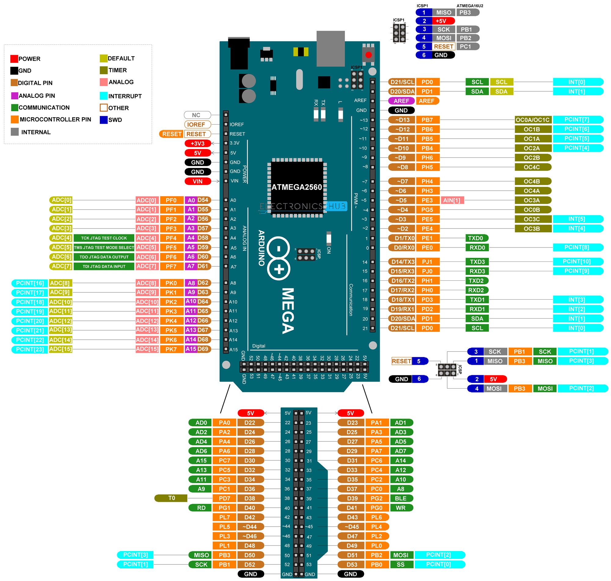
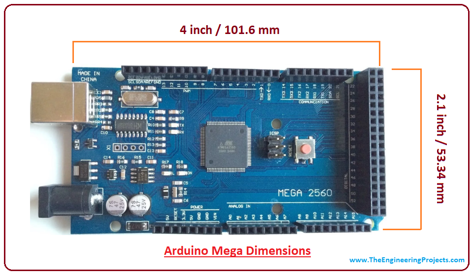
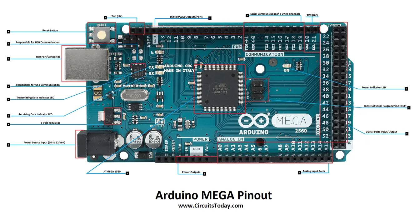
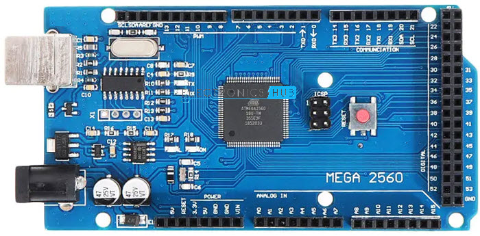
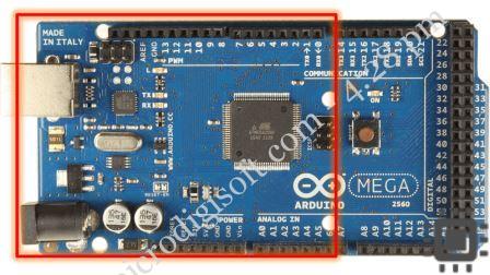
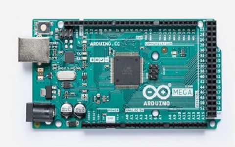
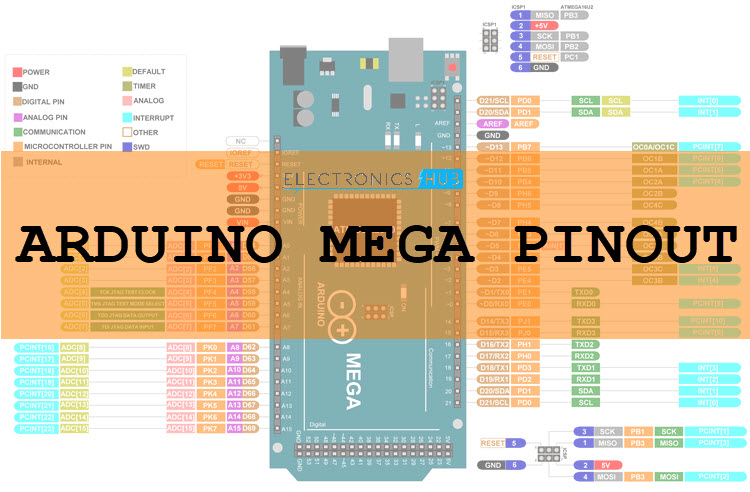
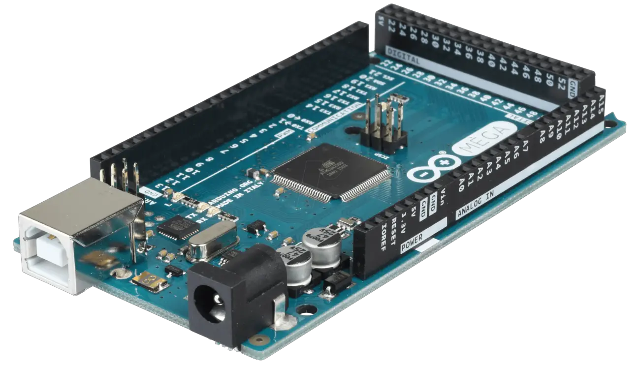
Ultimate Guide to Arduino Mega 2560 Pinout, Specs & Schematic Arduino Mega 2560 has 54 digital input/output pins, where 16 pins are analog inputs, 14 are PWM pins, and 6 are hardware serial ports (UARTs). It has a crystal oscillator-16 MHz, a power jack, an ICSP header, a USB-B port, and a RESET button. Arduino Mega Pinout. Voltage Regulator -The voltage regulator converts the input voltage to 5V. The K3NG Arduino CW Keyer – Radio Artisan Aug 27, 2020 · I had the same problem. It was kind of a hardware problem. The Arduino can only load round about 28 Kb of code. Try to comment some code so that you get under the magic number. At least it worked for me. And that was one of the reasons I still consider using the cw-keyer with the LCD-Shield with a Mega-Arduino. My Adafuit shield arrived today.
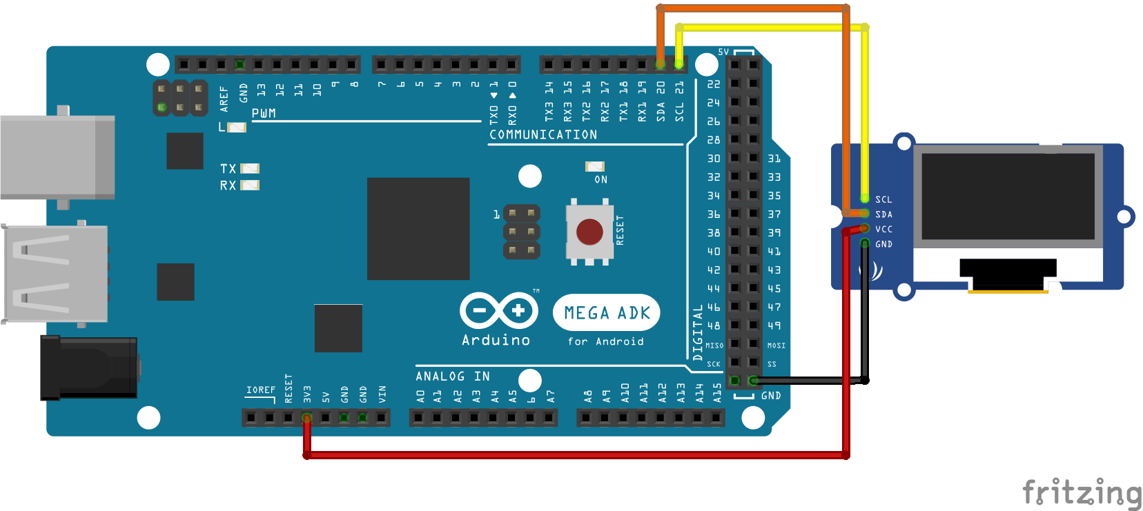
Fun With OLED Display and Arduino - Instructables Remember to check the labels of the pins on your modules to make sure you’re connecting it in a right way. We need only 4 pins that should be connected as below: Arduino VCC -> OLED Module VCC. Arduino GND -> OLED Module GND. Arduino 4 -> OLED Module SDA. Arduino 5 -> OLED Module SCK
Iic pin labels in arduino mega are
Amazon.com: KEYESTUDIO Mega Plus 2560 R3 Board for Arduino with Type-C ... This Mega Plus board can work like the Arduino Mega R3 2560 but it is more powerful and has more pins. The USB-to-Serial chip of this board is stable and compatible CP2102; USB connector of it is Type C USB Port; Up to 5V, 1.5A output, can drive drive high-current devices like servo and motor. Additional SPI communication interface, IIC communication interface, Serial communication interface (4 channel); Serial2 (D17 is RX2, D16 equals to TX2), Serial3 (D15 is RX3, D14 is TX3), D0 and D1 are ... arduino mega - Confused between SPI and I2C for SSD1306 OLED - Arduino ... Confused between SPI and I2C for SSD1306 OLED. I haven't been able to successfully wire it to an Arduino (Mega 2560) however. I have been reading up on I2C and SPI and checked some libraries from Adafruit and U8G2. However, I'm confused, since most of the Internet is talking about a similar OLED display with GND - VDD - SCL - SDA labelled pins ... Electronics Hub - Tech Reviews | Guides & How-to | Latest Trends Electronics Hub - Tech Reviews | Guides & How-to | Latest Trends
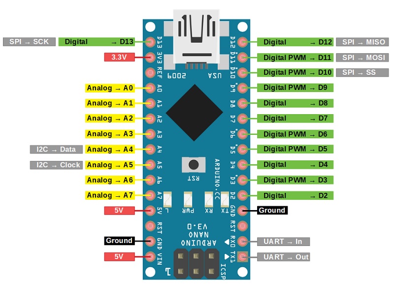
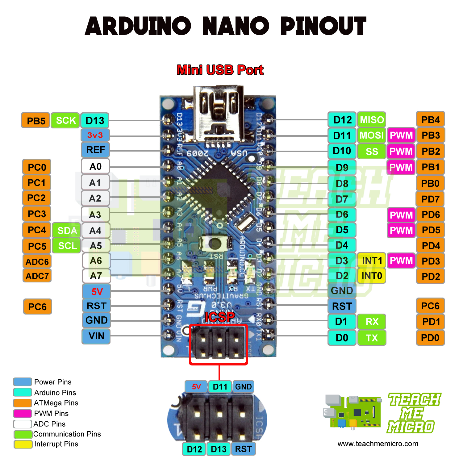
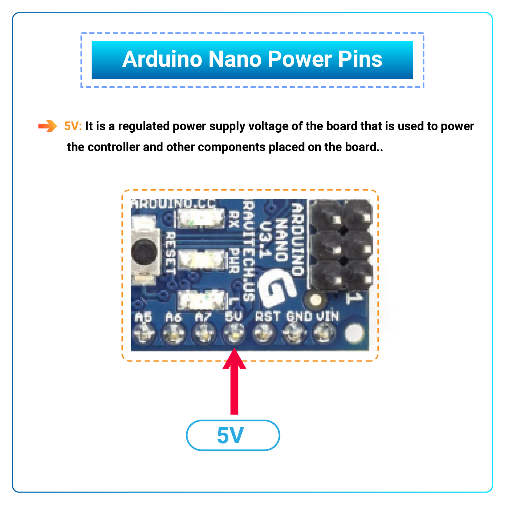
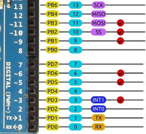
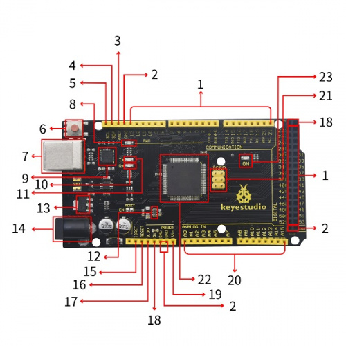
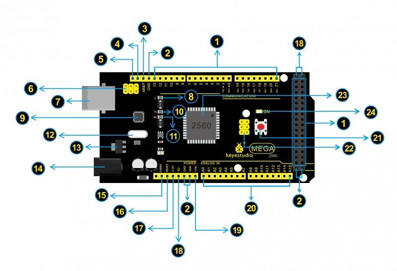
Iic pin labels in arduino mega are. Arduino-board/KS0002.md at main · keyestudio/Arduino-board KS0002 Keyestudio MEGA 2560 R3 development board. Introduction: Keyestudio Mega 2560 R3 is a microcontroller board based on the ATMEGA2560-16AU, fully compatible with ARDUINO MEGA 2560 REV3. It has 54 digital input/output pins (of which 15 can be used as PWM outputs), 16 analog inputs, 4 UARTs (hardware serial ports), a 16 MHz crystal oscillator, a USB connection, a power jack, 2 ICSP headers ... I2C Communications Part 1 - Arduino to Arduino - DroneBot Workshop Arduino Wire Library. The Arduino has a built-in library for working with I2C called the Wire Library. It makes it very easy to communicate on the I2C bus, and it can configure the Arduino to become either a master or a slave. The Wire library has several useful functions for working with I2C. I2C Tutorial for Arduino, ESP8266 and ESP32 - DIYI0T Arduino Mega. SDA: PIN20 SCL: PIN21 (no label on the PCB front, only visible from the side) The two pins which you need for the I2C communication are the following: ... If you like to know how you can reduce the number of input pins for a keypad from 8 to only 2 I2C pins, with the help of the I2C multiplexer, then visit the keypad tutorial for ... Arduino Nano: Pinout, Wiring Diagram and Programming - Diystadium Digital Pins D0 - D13: Input/Output Pins: Can be used as input or output pins. 0V (low) and 5V (high) (0) Rx, (1) Tx: Serial: The pins are used to receive (Rx) and transmit (Tx) TTL serial data. 2, 3: External Interrupts: The pins are used to trigger an interrupt on a low value or a change in value, a rising or falling edge. 3, 5, 6, 9, 11: PWM
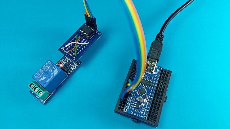
Arduino Mega Keyestudio - Mero Tronics Keyestudio Mega 2560 compatible Advanced is a microcontroller board based on the ATMEGA2560-16AU , fully compatible with Keyestudio Mega 2560 R3 board and ARDUINO MEGA 2560 REV3.It has 54 digital input/output pins (of which 15 can be used as PWM outputs), 16 analog inputs, 4 UARTs (hardware serial ports), a 16 MHz crystal oscillator, a USB connection, a power jack, 2 ICSP headers, and a reset button.It contains everything needed to support the microcontroller. introduction to Arduino nano Pin Category. Pin Name. Details. Power. Vin, 3.3V, 5V, GND Vin: Input voltage to Arduino when using an external power source (6-12V). 5V: Regulated power supply used to power microcontroller and other components on the board. 3.3V: 3.3V supply generated by on-board voltage regulator. Maximum current draw is 50mA. GND: Ground pins. Reset. Reset. Resets the microcontroller. KS0002 Keyestudio MEGA 2560 R3 development board — Board for Arduino ... SDA IIC communication pin. SCL IIC communication pin. ICSP (In-Circuit Serial Programming) Header the AVR, an Arduino micro-program header consisting of MOSI, MISO, SCK, RESET, VCC, and GND. Connected to the ATMEGA16U2-MU. When connecting to PC, program the firmware to ATMEGA16U2-MU. USB Connection Arduino board can be powered via USB connector. All you needed to do is connecting the USB port to PC using a USB cable. Arduino Micro Pro Pin Out - Walmart.com Shop for Arduino Micro Pro Pin Out at Walmart.com. Save money. Live better. Skip to Main Content. ... 5V Relay Module with Optocoupler Low Level Trigger Expansion Board for Arduino R3 MEGA 2560 1280 DSP ARM PIC AVR STM32 Raspberry Pi. Reduced price. Add. $10.99. ... 0.91 4 Pin IIC Serial 128x32 White/Blue OLED LCD LED Display Module For Arduino.
KEYESTUDIO 10PCS Proto Shield for Arduino Mega, Double Sided PCB ... Amazon.com: KEYESTUDIO 10PCS Proto Shield for Arduino Mega, Double Sided PCB Prototype Shield Solderable for Arduino Mega R3 2560 ... MakerFocus I2c OLED Display 0.96 Inch IIC Serial LCD LED Module SSD1306 128 64 for Ar duino with 40pcs Du pont Wire 20CM 40-Pin Female to Female ... Black mask, silver tone, yellow pins label - Hole-pitch: 2.54 ... Arduino - OLED | Arduino Tutorial - Arduino Getting Started VCC pin: is the power supply for the display which we connect the 5 volts pin on the Arduino. SCL pin: is a serial clock pin for I2C interface. SDA pin: is a serial data pin for I2C interface. Raspberry Pico SPI and I2C pins #194 - GitHub I downloaded a fresh Arduino IDE, Removed all Arduino related libs from my user and started the IDE. I went to the Board Manager an installed 'Arduino OS RP2040 Boards'. I selected the 'Raspberry PI Pico' board. I uploaded the Blink sketch pressed upload (which failed) I Ran the post-install.sh (from your repo) as root. This fixed the above issue! Arduino Nano - Components101 Arduino Mega is more powerful than an Arduino Nano in terms of speed and number of I/O pins. As you might guess, the size is also bigger than an Arduino UNO. Arduino Mega is normally used for projects which require a lot of I/O pins and different communication protocols. The technical difference between Nano and Mega is shown below.
Arduino Pin Configuration: A Detailed Guide (2021) | Robu.in
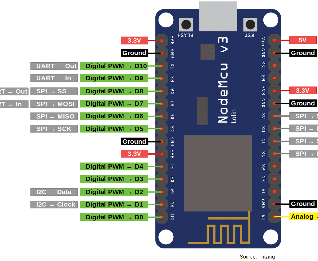
ESP8266 Pinout Reference: Which GPIO pins should you use? The following table shows the correspondence between the labels on the silkscreen and the GPIO number as well as what pins are the best to use in your projects, and which ones you need to be cautious. ... GPIO0 to GPIO15. PWM signals on ESP8266 have 10-bit resolution. Learn how to use ESP8266 PWM pins: ESP8266 PWM with Arduino IDE; ESP8266 PWM ...
Arduino Uno Pins - A Complete Practical Guide - The Robotics ...
Character I2C LCD with Arduino Tutorial (8 Examples) - Makerguides.com SDA and SCL pin locations on different Arduino boards. Adjusting the contrast of the LCD. After you have wired up the LCD, you will need to adjust the contrast of the display. On the I2C module, you will find a potentiometer that you can turn with a small screwdriver. Plug in the USB connector of the Arduino to power the LCD.
Arduino NANO Pinout Diagram | Microcontroller Tutorials
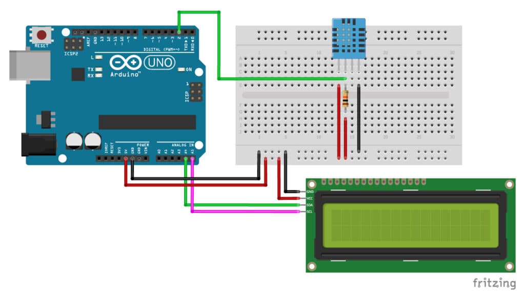
Using I2C SSD1306 OLED Display With Arduino - Electronics-Lab An Arduino, (Arduino Mega in this tutorial) Power source, Powerbank, Battery, or USB cable. Wires. The Circuit. The circuit is very simple. First, connect the GND with Arduino GND, VCC with 3.3V or 5V on Arduino, SCL with SCL, and finally SDA with SDA pin. Upload the code and power on the Arduino.

Arduino Due Overview - Legacy Personal Blogs - Personal Blogs ...
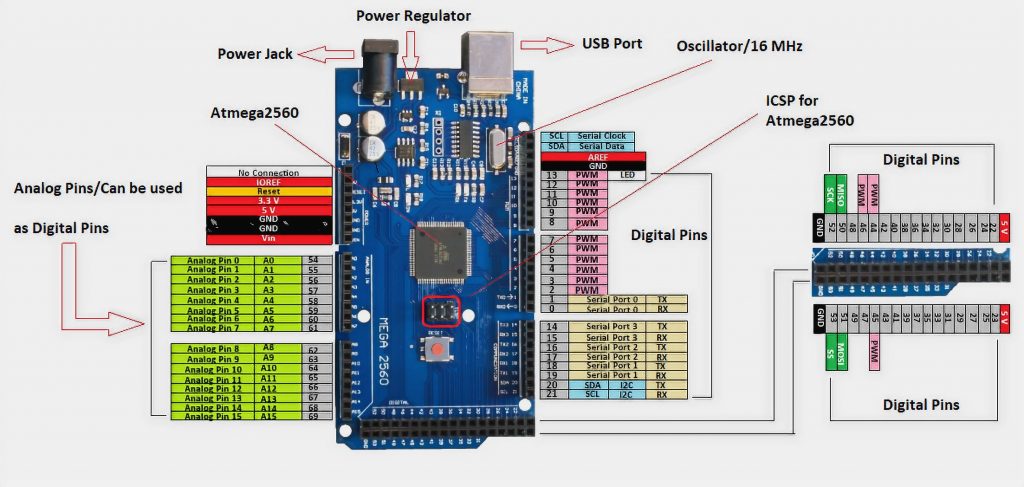
arduino-info - LCD-Blue-I2C - UPM But you can wire it directly yourself if needed: There are 4 pins on the display.. (see photo below) Top to bottom: GND - GND VCC - 5V SDA - ANALOG Pin 4 SCL - ANALOG pin 5 On most Arduino boards, SDA (data line) is on analog input pin 4, and SCL (clock line) is on analog input pin 5. On the Arduino Mega, SDA is digital pin 20 and SCL is 21.

Arduino Nano Pinout, Specifications, Features, Datasheet ...
Gravity: HUSKYLENS - An Easy-to-use AI Machine Vision Sensor In this project, HuskyLens will be connected to Arduino mainboard. And Arduino Uno will read position data of the object from HuskyLens. Then the serial port monitor will print the data. So that, you can read the position of the object in real time. Requirements. Hardware. DFRduino UNO R3 (or similar) x 1; HUSKYLENS x 1; M-M/F-M/F-F Jumper ...

Arduino Uno - Wikipedia
FamilyAlbum | L'appli de partage photos et vidéos en famille Déjà plus de 15 millions d'utilisateurs ! Avec FamilyAlbum, partagez en privé et sauvegardez en illimité les photos et vidéos des enfants. Gratuit et sans pub !
DHT11/DHT22 Sensor with Arduino Tutorial (2 Examples)
Using a 20×4 I2C Character LCD display with Arduino Uno For the Arduino Uno, the I2C pins are located on Pin A5 (SCL) and A4 (SDA). This may differ on any of the other Arduino boards. Connect the components as shown in the schematics below; Schematics To make the connections, even more easier to follow, the pin connections of the components is described below. Arduino - LCD

Arduino UNO Pinout (Diagram) Learn quickly pins function
Wire - Arduino Reference Description This library allows you to communicate with I2C/TWI devices. On the Arduino boards with the R3 layout (1.0 pinout), the SDA (data line) and SCL (clock line) are on the pin headers close to the AREF pin. The Arduino Due has two I2C/TWI interfaces SDA1 and SCL1 are near to the AREF pin and the additional one is on pins 20 and 21.
Arduino Mega Pinout | Arduino Mega 2560 Layout, Specifications
Arduino and the SSD1306 OLED I2C 128x64 Display If you are not using an Arduino UNO the SDA and SCL connections might be on different pins. On a MEGA or Leonardo SDA goes to pin 20 and SCL to pin 21. Take care as some SSD1306 boards have their pins in a different order - use the labels not the relative positions. Add Tip Ask Question Comment Download Step 2: Check the I2C Address

I2C Communications Part 1 - Arduino to Arduino | DroneBot ...
Arduino Mega Tutorial - Pinout & Schematics - Electronic Circuits and ... "Pin 22 - SS, Pin 23 - SCK, Pin 24 - MOSI, Pin 25 - MISO" The ATmega2560 datasheet for SPI shows: Pin 19 - SS, Pin 20 - SCK, Pin 21 - MOSI, Pin 22 - MISO. (arduino pin mapping: SS=53, SCK=52, MOSI=51, MISO=50)
Introduction to Arduino Mega 2560 - The Engineering Projects
IIC I2C TWI SPI Interface Module PCF8574T for Arduino 1602 LCD 2004 ... Arduino IIC I2C interface Color: black Material: CCL LED 1602/2004 adapter board (not included LED screen) Pin Definition : GND,VCC,SDA,SCL Supply voltage: 5V Size :5.2cm*1.8cm*1.4cm Compatible for 1602 LCD 2004 LED Package included:1x PCF8574T module Note: Light shooting and different displays may cause the color of the item in the picture a little different from the real thing. The measurement allowed error is +/- 1-3cm.
Arduino UNO Pinout, Specifications, Board Layout, Pin Description
Interfacing Arduino with BMP280 pressure and temperature sensor D5 —> Arduino digital pin 5 D6 —> Arduino digital pin 6 D7 —> Arduino digital pin 7 VSS, RW, D0, D1, D2, D3 and K are connected to Arduino GND (ground) VEE to the variable resistor (or potentiometer) output VDD to Arduino 5V and A to Arduino 5V through 330 ohm resistor. VEE pin is used to control the contrast of the LCD. A (anode) and K ...

LCD + MEGA 2560 Incorrect wiring on the Compiling program ...
keyestudio Mega 2560 Plus Board - techmoversph.com I bought my first gaming PC (Ryzen 5 3600 & RTX 2060 Super) before the pandemic. I started to notice that the prices of computer parts started to increase to the point that they were just so absurd. I remember seeing Ryzen 5 3600 being sold at 13k. So I decided to intervene.
Arduino Mega Tutorial - Pinout and Schematics. Mega 2560 ...
Two Arduino Mega 2560 I2C There is a trace on the Arduino board connecting the pins on the chip to labeled locations around the periphery of the board. The labels around the periphery correspond to what the code expects to have stuff connected to. system January 30, 2015, 12:12pm #3
Using I2C SSD1306 OLED Display With Arduino - Electronics-Lab.com
ELECHOUSE PN532 NFC RFID Module User Guide - Manuals+ It could be connected directly to the 5V interface of a microcontroller such as Arduino. The I2C and HSU share the same pins. The definition of IIC pins is printed at the front and the HSU's is printed at the back. The HSU mode is configured as the default mode. But you could change the interface by setting the toggle switch.

What pins to use for I2C bus with AVR Mega2560 - Programming ...
Electronics Hub - Tech Reviews | Guides & How-to | Latest Trends Electronics Hub - Tech Reviews | Guides & How-to | Latest Trends

Cannot Get Serial Communications From WEMOS D1 Mini to ...
arduino mega - Confused between SPI and I2C for SSD1306 OLED - Arduino ... Confused between SPI and I2C for SSD1306 OLED. I haven't been able to successfully wire it to an Arduino (Mega 2560) however. I have been reading up on I2C and SPI and checked some libraries from Adafruit and U8G2. However, I'm confused, since most of the Internet is talking about a similar OLED display with GND - VDD - SCL - SDA labelled pins ...

I2C Communications Part 1 - Arduino to Arduino | DroneBot ...
Amazon.com: KEYESTUDIO Mega Plus 2560 R3 Board for Arduino with Type-C ... This Mega Plus board can work like the Arduino Mega R3 2560 but it is more powerful and has more pins. The USB-to-Serial chip of this board is stable and compatible CP2102; USB connector of it is Type C USB Port; Up to 5V, 1.5A output, can drive drive high-current devices like servo and motor. Additional SPI communication interface, IIC communication interface, Serial communication interface (4 channel); Serial2 (D17 is RX2, D16 equals to TX2), Serial3 (D15 is RX3, D14 is TX3), D0 and D1 are ...

4. Arduino Technical Details - Arduino: A Technical Reference ...
Arduino Mega Pinout | Arduino Mega 2560 Layout, Specifications
![The Full Arduino Uno Pinout Guide [including diagram]](https://images.prismic.io/circuito/8e3a980f0f964cc539b4cbbba2654bb660db6f52_arduino-uno-pinout-diagram.png?auto=compress,format)
The Full Arduino Uno Pinout Guide [including diagram]
Introduction to Arduino Nano - The Engineering Projects

Multiple I2C Buses with an Arduino and TCA9548A Module
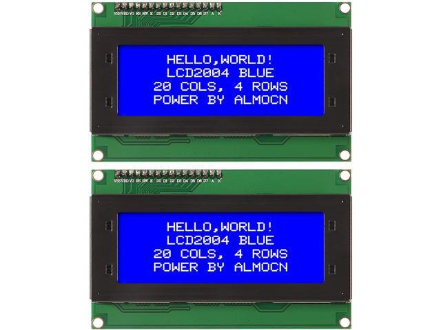
ALMOCN 2 Pack IIC I2C TWI Serial 2004 20x4 LCD Display Module with I2C Interface Adapter Blue Backlight for Arduino UNO R3 MEGA2560(2 Pack 2004 Blue)
I2C Tutorial for Arduino, ESP8266 and ESP32
Arduino Uno Pins - A Complete Practical Guide - The Robotics ...

Can I reassign SPI pins on an Arduino UNO? - Programming ...
![The Full Arduino Uno Pinout Guide [including diagram]](https://images.prismic.io/circuito/0f83e727bd5b62cfcfbaea10eb1de83ffb3af5ba_arduino-uno-pinout-power-supply.png?auto=compress,format)
The Full Arduino Uno Pinout Guide [including diagram]
INTRODUCTION TO Arduino mega 2560 - microdigisoft.com

4. Arduino Technical Details - Arduino: A Technical Reference ...
KS0498 Keyestudio MEGA 2560 R3 Development Board(Compatible ...
Arduino Mega 2560 Board: Specifications, and Pin Configuration
Arduino Mega Pinout | Arduino Mega 2560 Layout, Specifications
Arduino Mega Pinout Guide (ATmega2560) - NerdyTechy
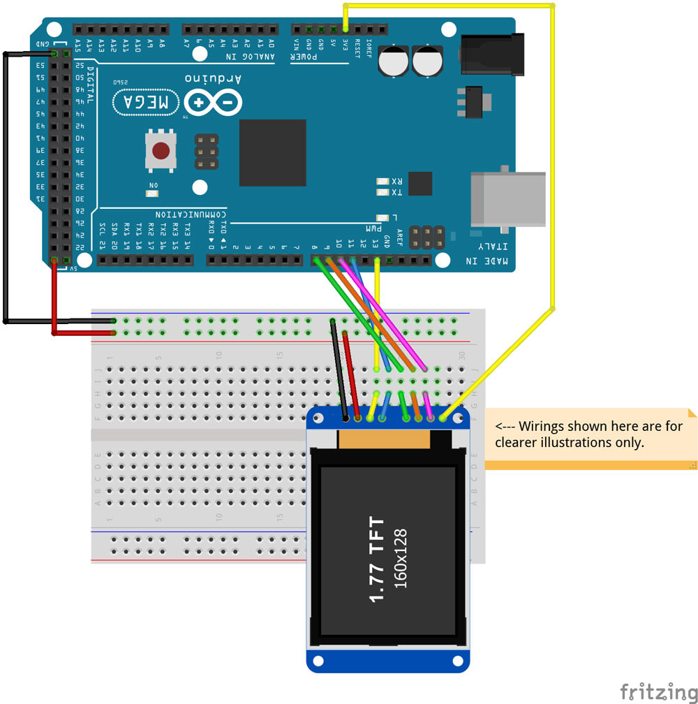
1.77 Inch TFT LCD Display with ST7735S on Arduino Mega 2560
Posts with «i2c» label
Arduino Mega Tutorial - Pinout and Schematics. Mega 2560 ...

Guide for I2C OLED Display with Arduino | Random Nerd Tutorials
Ks0002 keyestudio Mega 2560 R3 Development Board - Keyestudio ...

Block Diagram 1. ArduinoMEGA2560: The Arduino Mega 2560 is a ...
![The Full Arduino Uno Pinout Guide [including diagram]](http://images.prismic.io/circuito/c255f16a2d6719264ffc5e61a3288197b91f865e_arduino-uno-pinout-guide.png?auto=compress,format)
The Full Arduino Uno Pinout Guide [including diagram]

Interface I2C 16x2 LCD with Arduino Uno (Just 4 wires ...
Post a Comment for "42 iic pin labels in arduino mega are"